Minerva BR-1 Block 0 0 / 41

Georgia Wing High Power Rocketry

Minerva BR-1 Block 0
Assembly Instructions

Block 0 build guide — Georgia Wing High Power Rocketry, Civil Air Patrol

41 steps 13 videos 7 stages Progress saves on this device
QR code linking to this guide Scan to follow along on your phone blinksoft.github.io/minerva-br1-instructions

Before you start

Read the whole page once before you open the epoxy. Several steps have a cure wait built in, and knowing what is coming keeps you from gluing yourself into a corner.

Work on a covered bench. Epoxy does not come off finished furniture.

Dry-fit every part before it gets glue on it. Every step that says "test fit" is there because parts vary.

Your body tube is white. Some photos in this guide show an older kraft-brown tube — the parts and steps are the same.

Safety

Epoxy is a skin sensitizer. Every exposure raises the odds of a permanent allergic reaction, so wear nitrile gloves whenever you mix, spread or clean up epoxy. Never wipe it off skin with solvent; wash with soap and water.
Wear eye protection when sanding, when mixing epoxy, and whenever you use superglue. Superglue can spatter, and it bonds to the eye instantly.
Work in a ventilated area. Epoxy and superglue fumes build up fast in a closed room.
Superglue bonds skin instantly. Keep acetone or debonder nearby, and never put your finger behind a hole you are about to glue into unless the step tells you to.
No motors, igniters, or black powder anywhere near the build table.

00Parts & Tools

Lay everything out and check it off before you start. Tell your instructor now if something is missing.

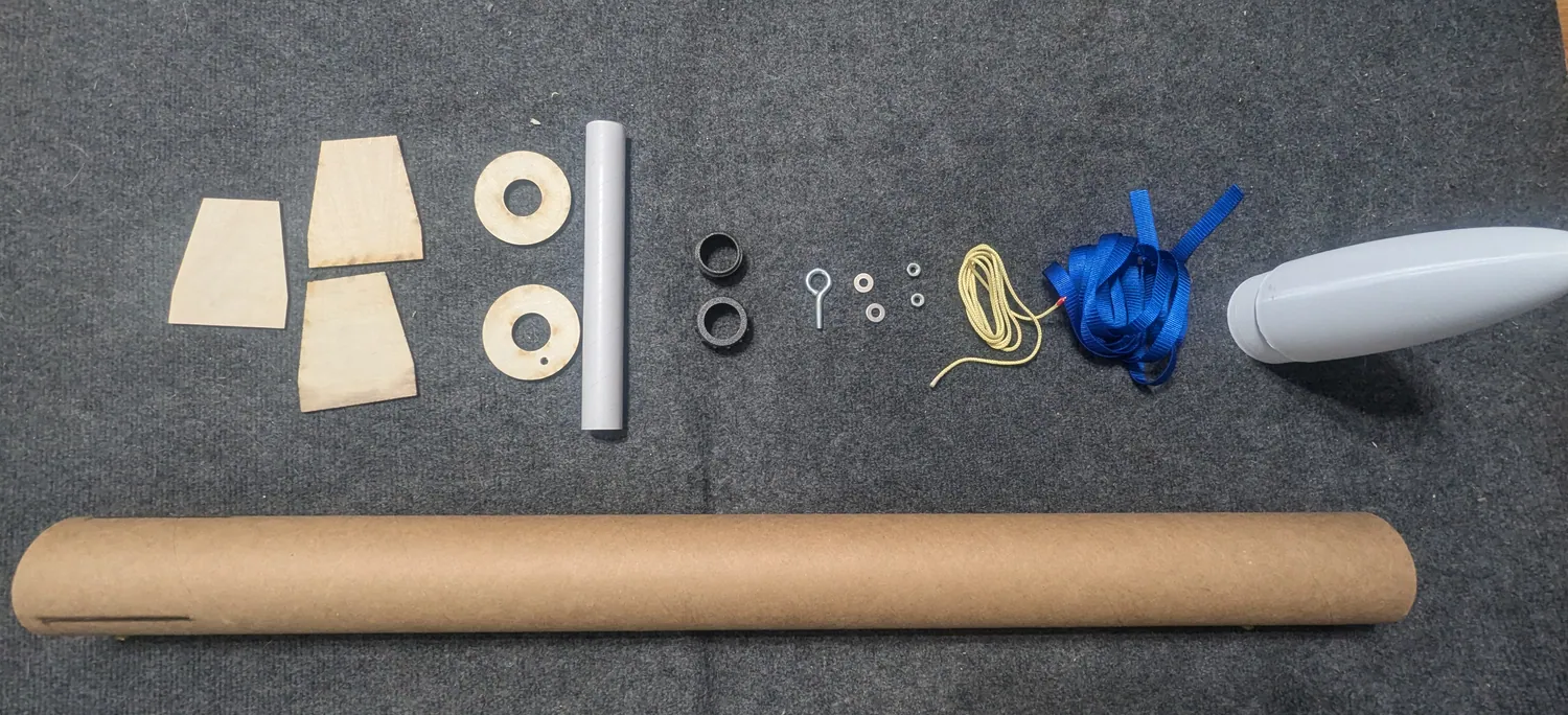
Everything that comes in the Minerva BR-1 Block 0 kit, laid out.

Kit parts

Tools needed

Build sequence

  1. Rail Buttons · 3 steps
  2. Motor Mount · 13 steps
  3. Eyebolt & Recovery Anchor · 6 steps
  4. Install the Motor Mount · 6 steps
  5. Fins · 8 steps
  6. Recovery Harness · 3 steps
  7. Finish & Homework · 2 steps

01Rail Buttons

These go on the body tube, not the motor mount. Do them first — once the motor mount is glued inside, you cannot reach the forward hole.

Watch: What is high power rocketry?

Before the build starts. On build day this plays during the Alpha III glue wait.

What makes a rocket “high power” instead of a model rocket, and which of the two rockets on the table is which.


Install the forward rail button

The forward hole is too far down the tube to reach with a finger, so the weld nut gets pulled into place with a piece of 18–22 gauge wire about 24 inches long.
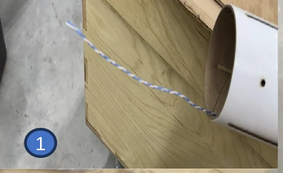
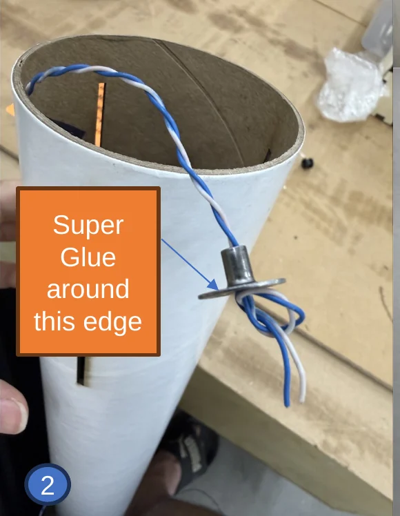
  1. Thread the wire in through the forward rail button hole from the outside and out the aft end of the tube.
  2. Slide the weld nut onto the wire, pointy side toward the inside of the tube. Tie an overhand knot (shoe knot) in the wire so the nut cannot come off.
  3. Put superglue around the weld nut, then gently pull the wire until the nut seats in the hole and the point is sticking out. Hold for 60 seconds while the glue sets.
  4. Cut the wire off right at the nut with scissors or wire cutters.
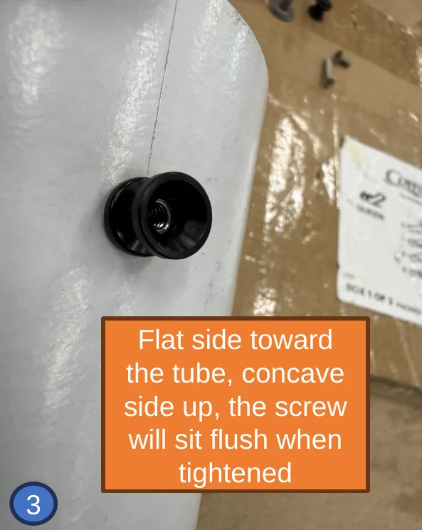
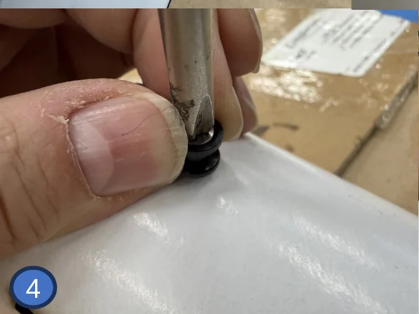
  5. Put the rail button on the nut — flat side toward the tube, concave side out — and start the screw by hand.
  6. Pull the rail button outward while you screw it down. Snug is good.
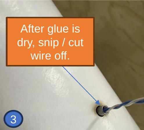
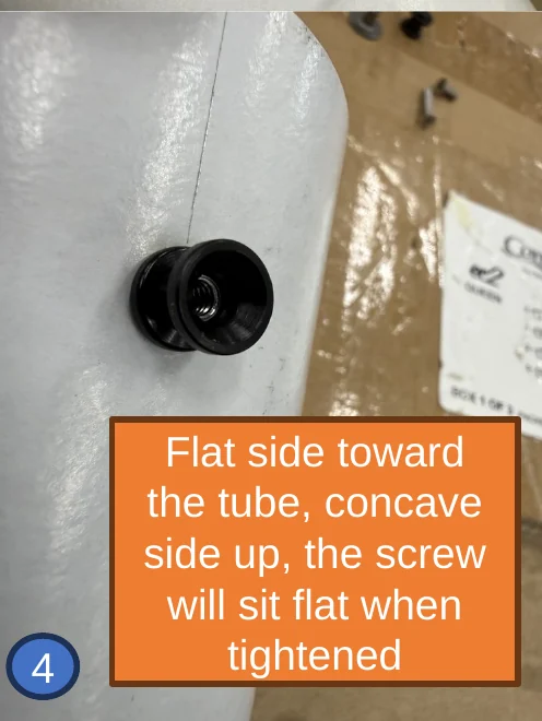
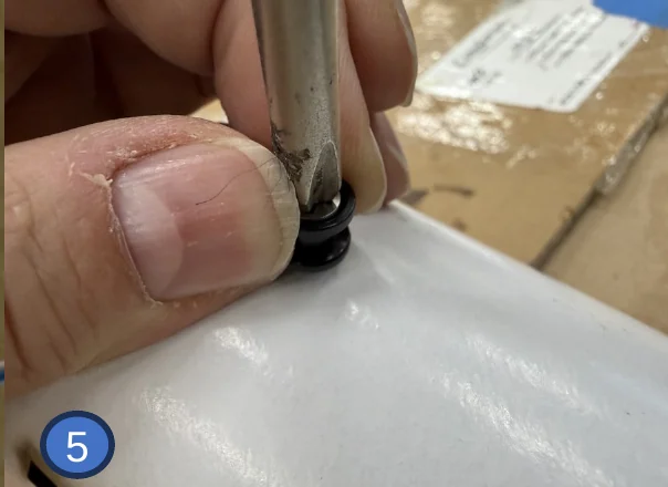
The numbered photos below match the numbered steps above — arrows and labels are from the original build briefing.
If you have never done this, do a test pull with no glue first.
Be very careful not to push the nut back into the body — you cannot get it back.
Do not overtighten. The rail button will crack.
1 — Wire threaded in through the rail button hole and back out the aft end of the tube.
2 — Weld nut on the wire with an overhand knot behind it. The arrow shows the edge the superglue goes around.
3 — Nut pulled up into the hole, wire still protruding. Hold 60 seconds, then snip the wire flush at the nut.
4 — Rail button on the nut: flat side toward the tube, concave side up, so the screw sits flat.
5 — Start the screw by hand, then pull the button outward as you tighten.
6 — Snug is good. Stop there.

Install the aft rail button

The aft hole is close enough to the end that you can hold the nut with a finger, so no wire needed.
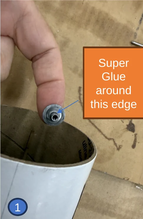
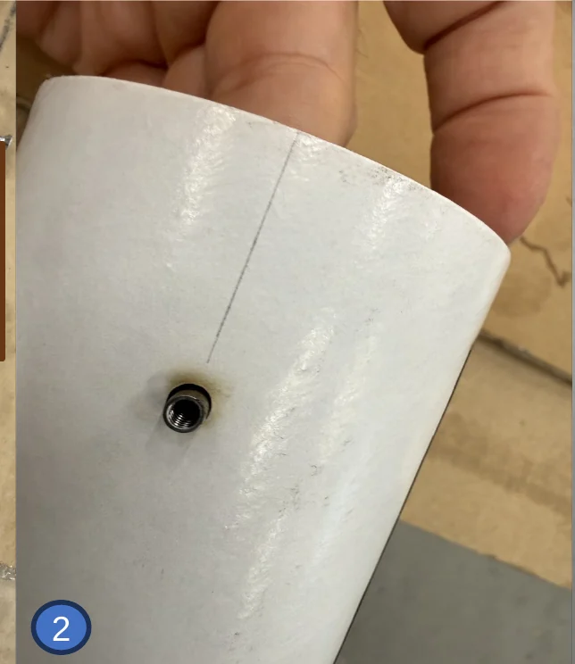
  1. Balance the weld nut on your fingertip and put superglue around its inner edge.
  2. Reach in through the aft end and press the nut into the hole from the inside.
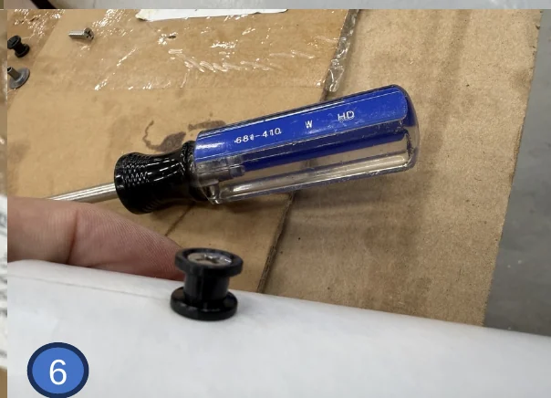
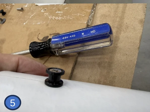
  3. Keep your finger on the back of the nut and put the rail button on — flat side toward the tube, concave side out. Start the screw by hand, then pull the button outward while you tighten it.
The numbered photos below match the numbered steps above — arrows and labels are from the original build briefing.
Practice putting the nut into the hole dry before you add glue.
Snug only. Do not crack the button.
1 — Weld nut balanced on a fingertip. The arrow shows the inner edge that gets the superglue.
2 — Nut pressed into the hole from inside and held there.
3 — Rail button on: flat side toward the tube, concave side up, so the screw sits flush.
4 — Start the screw by hand, pulling the button outward as you tighten.
5 — Snug is good. Do not crack the button.

02Motor Mount

Build the motor mount as its own subassembly. It has to be square and fully cured before it goes anywhere near the body tube.

Sand the motor mount tube

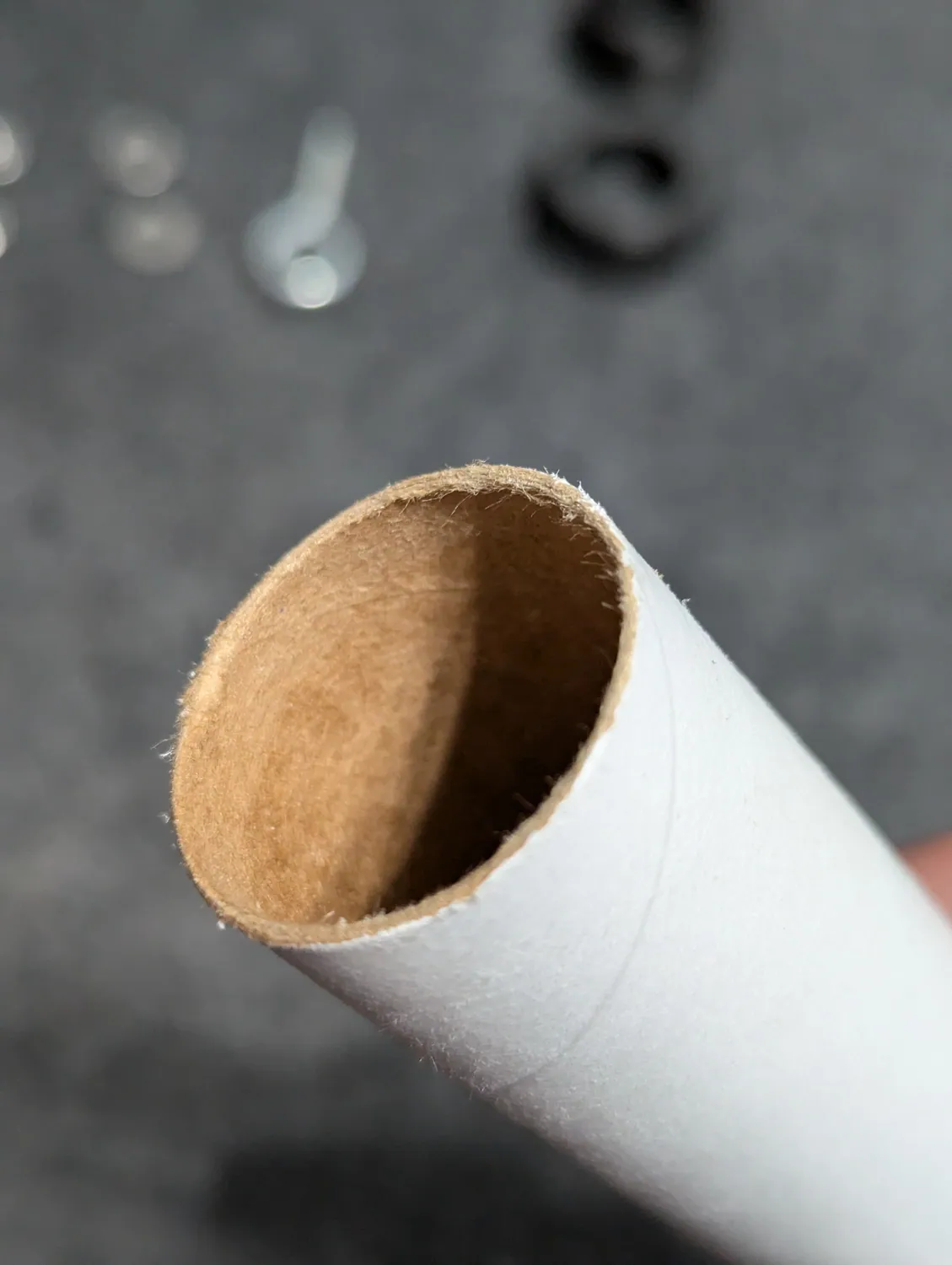
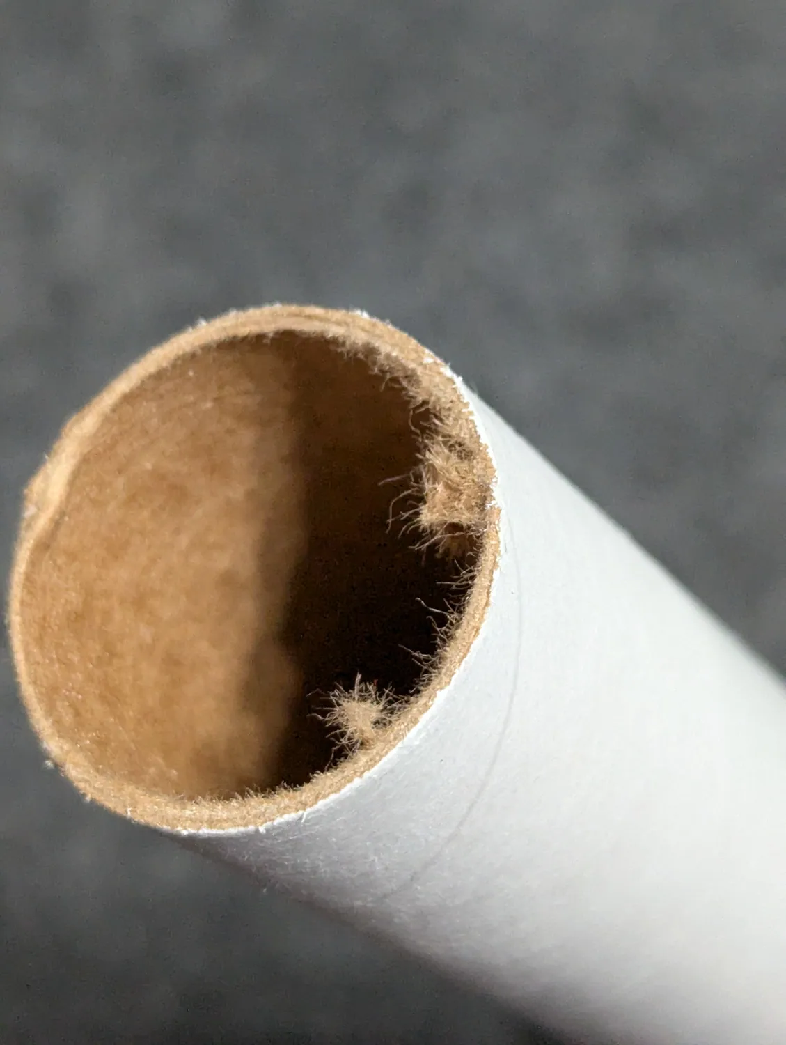
The cut ends of the motor mount tube usually have some fuzzy excess cardboard. Sand those smooth.

Sand the whole outside of the tube to knock off the shiny coating.
That glossy coating is what epoxy fails to stick to. Dull the entire surface the centering rings will sit on.
Cut end before sanding — note the loose cardboard fibers.
Same end cleaned up.

Test fit the centering rings

Slide each centering ring onto the motor mount tube. They should go on, but they should not be loose.

If a ring will not start, sand the inside diameter a little at a time and try again.
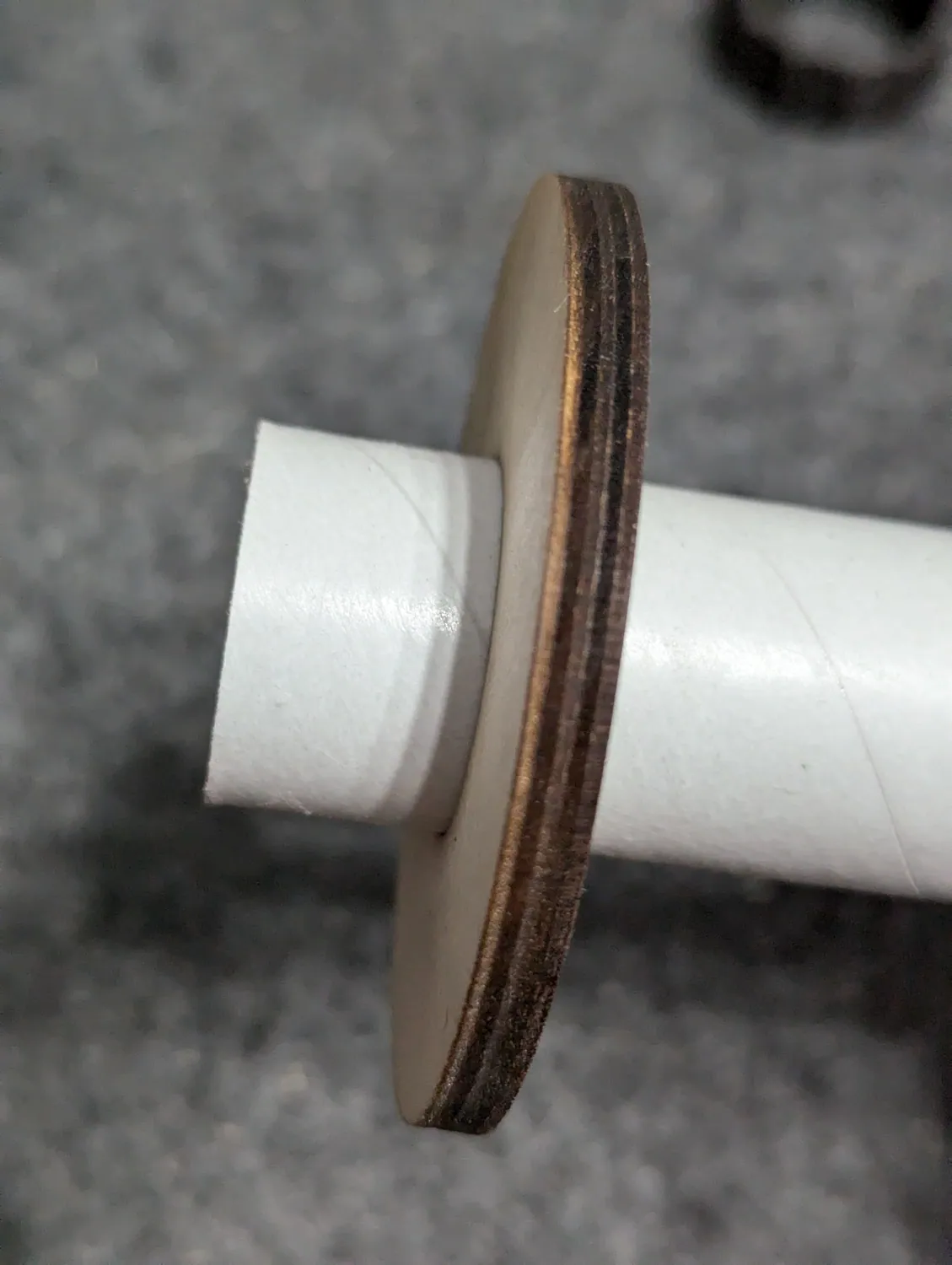
A tight fit is what you want. Sand the ring, not the tube — you already sized the tube in step 4.
Centering ring dry-fit on the motor mount tube.

Mark the aft end

Set the threaded end of the motor retainer onto the aft end of the motor mount tube.

Slide the aft centering ring down until it touches the retainer.

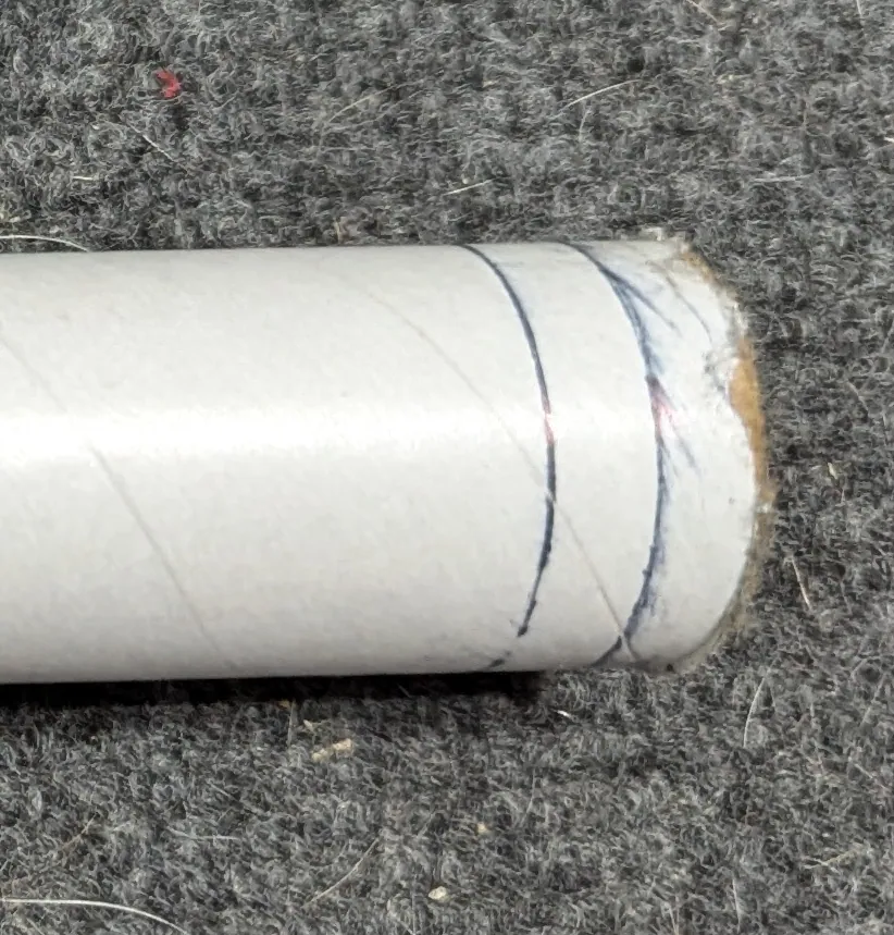
Mark all the way around the tube at the forward edge of the ring.
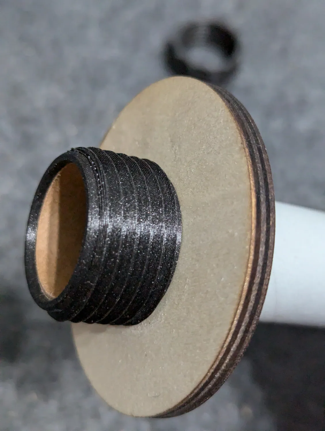
That line is the forward edge of your epoxy zone for step 9. Everything aft of it gets glue.
Motor retainer on the tube with the aft ring pushed up against it.

Mark the forward end

Make a mark ¼ inch down from the forward (top) end of the motor mount tube.

Slide the forward centering ring — the one with the eyebolt hole — down to that mark.

Mark all the way around the tube at both edges of the ring.
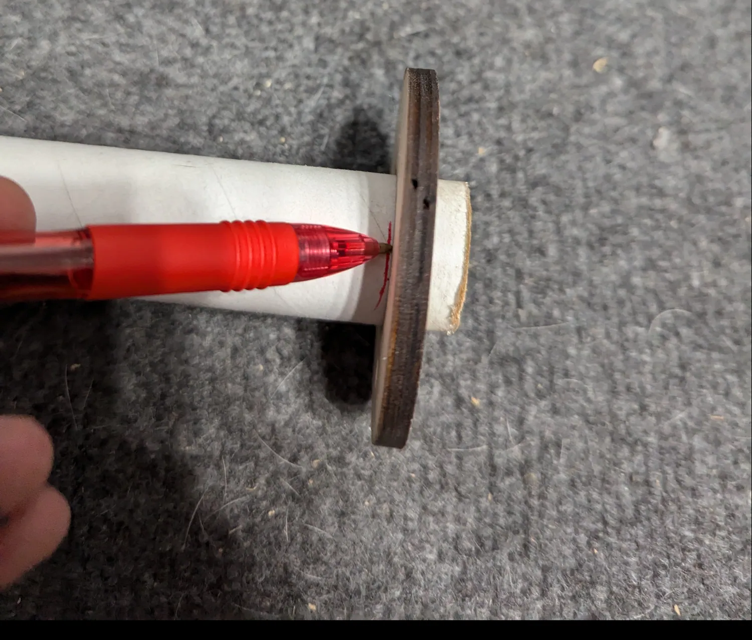
Marking around the tube at the edge of the forward ring.
Both reference lines marked on the tube.

Move the rings clear

Take the forward centering ring back off the tube.

Slide the aft centering ring to about the middle of the tube so it is out of the way.
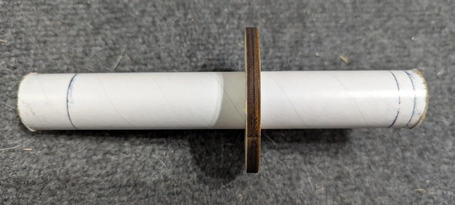
Aft ring parked mid-tube, forward ring removed.

Epoxy the motor retainer and aft centering ring

5-minute epoxy

Spread epoxy on the tube from the aft end up to the mark you made in step 6.

Slide the motor retainer on, then slide the aft centering ring down until it touches the retainer.

Check that the ring is square to the tube before the epoxy grabs.
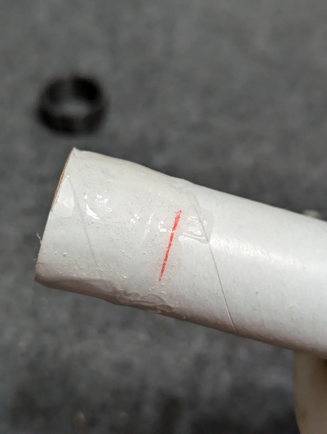
Do not get any epoxy inside the motor mount tube. If you do, wipe it out immediately with alcohol — a cured ridge inside the tube will keep the motor from seating.
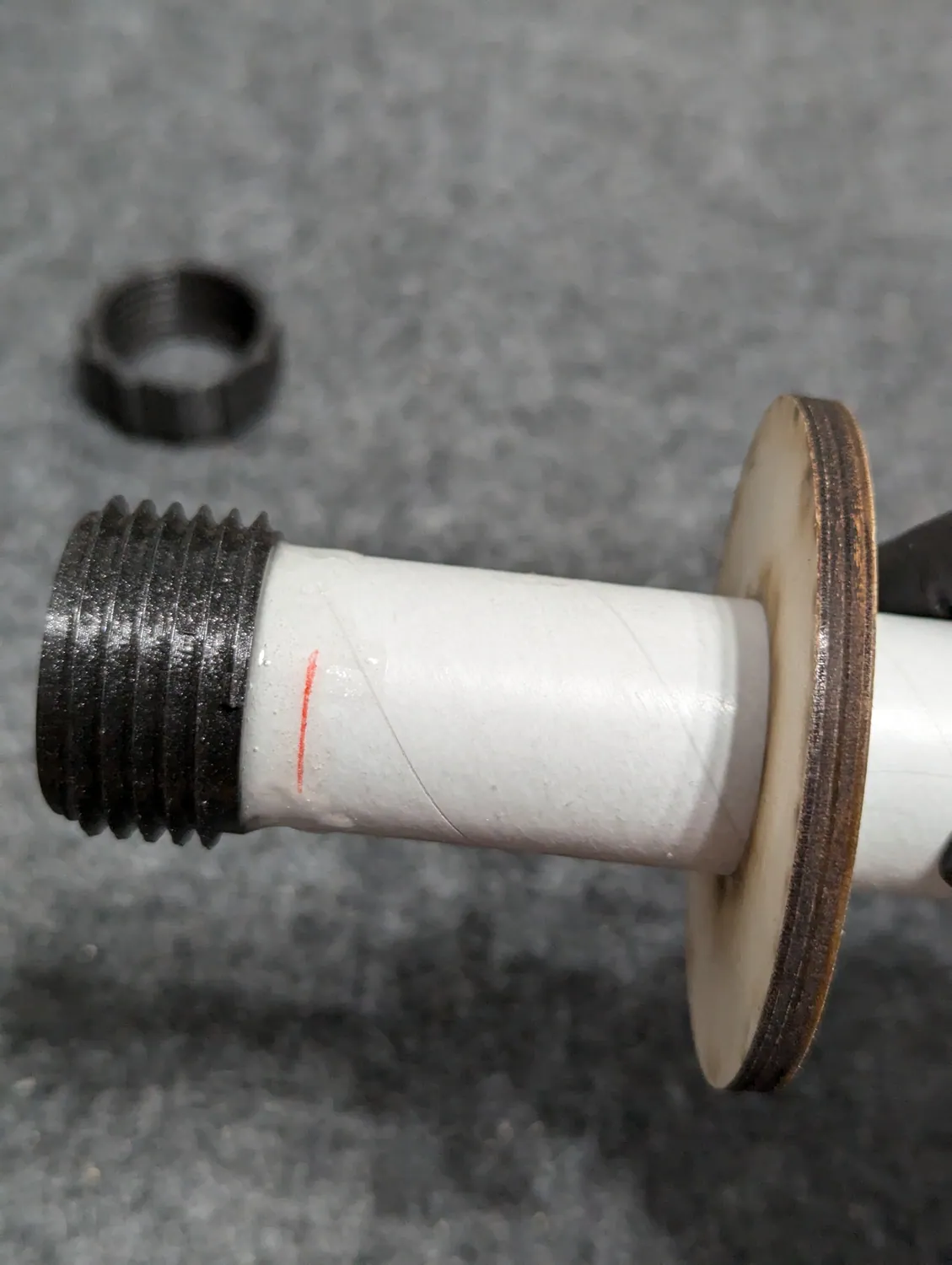
Keep epoxy off the retainer threads.
Epoxy spread between the aft end and the mark.
Retainer and aft ring slid into place against each other.
Assembled aft end — retainer, then centering ring.

Watch: NAR, Tripoli and certification

While step 9 sets.

The two national organizations, what a Level 1 certification is, and when you are old enough to try for one.

Epoxy the forward centering ring

5-minute epoxy

Run a band of epoxy all the way around the tube between the two forward marks.

Slide the forward centering ring down onto that band.
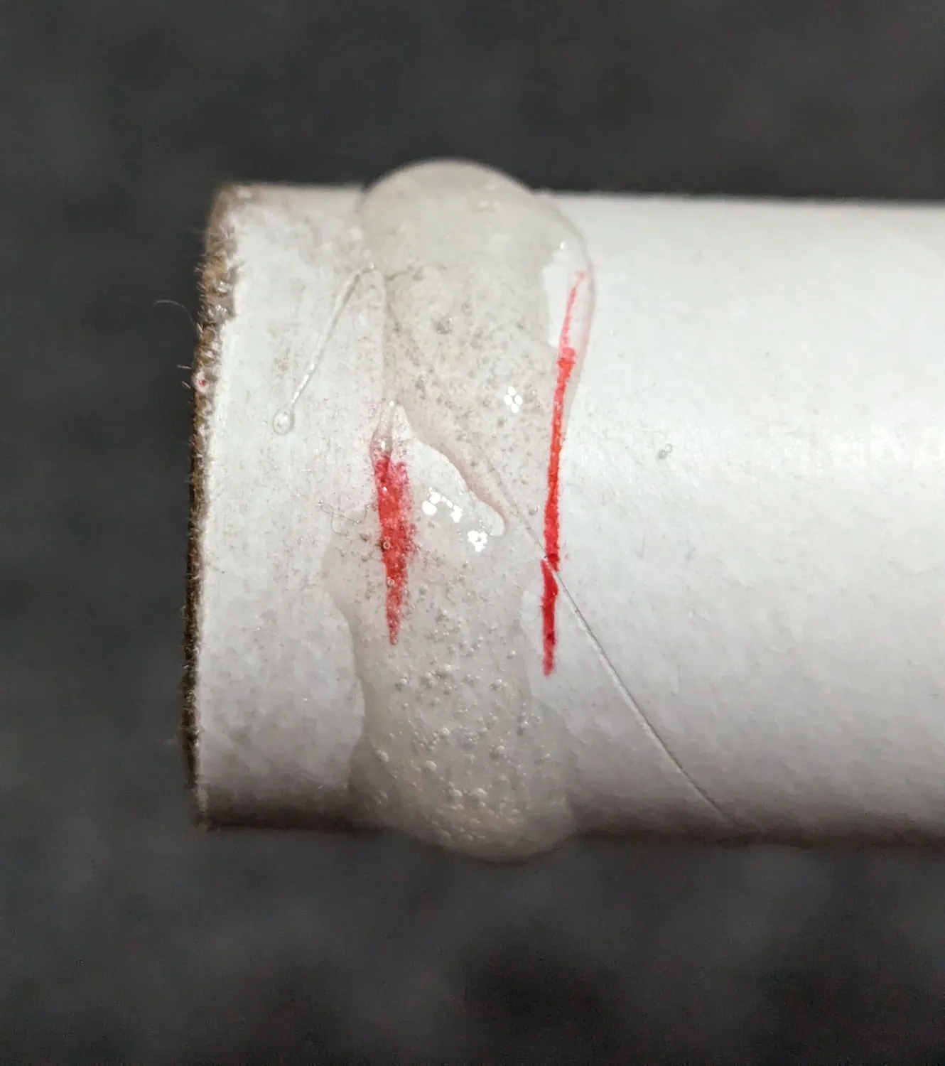
Get the ring perpendicular to the tube and hold it there. A cocked ring means the motor mount will not go into the body tube straight, and the whole rocket flies crooked.
Epoxy band applied between the two marks.
✓Ring square to the tube.
Ring square to the tube.
✕Ring cocked off-square — fix this before it cures.
Ring cocked off-square — fix this before it cures.

Let the motor mount cure

Stand the assembly up with the retainer end pointing up and leave it alone until the epoxy is hard.
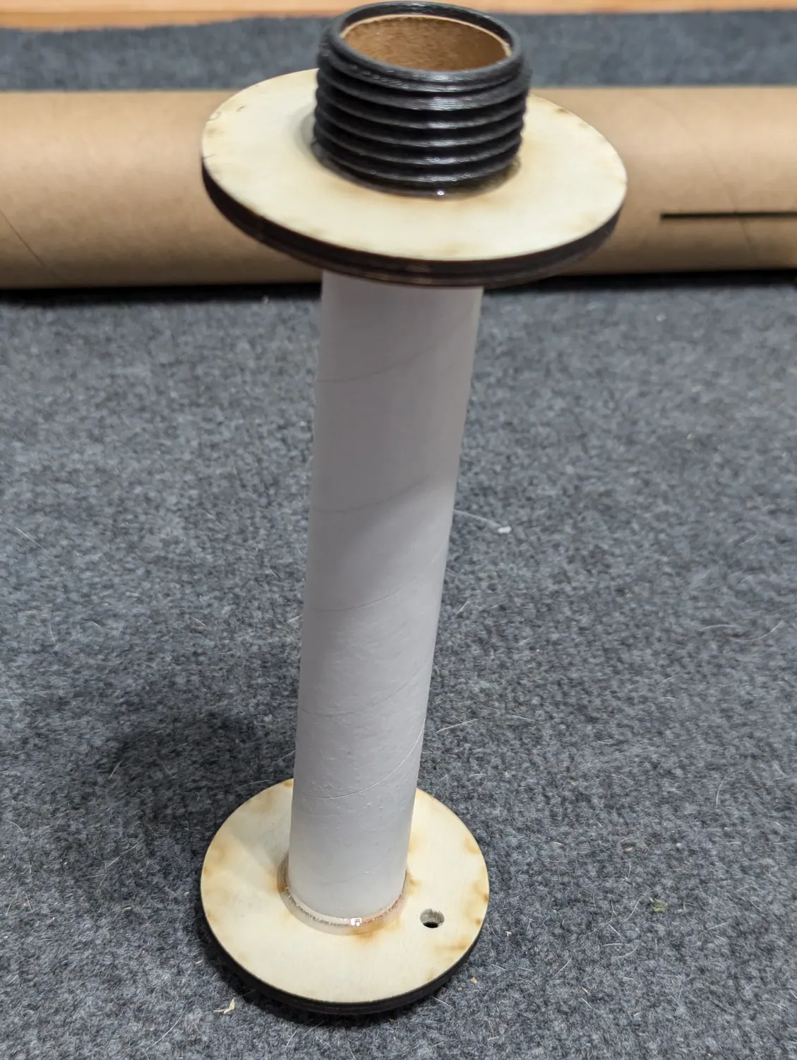
Standing it retainer-up lets gravity keep the rings seated instead of sagging.
Motor mount standing on the forward ring while it cures.

Watch: Center of pressure

While the motor mount cures (step 13), first video.

What the center of pressure is, which parts of the rocket make it, and why fins at the back move it aft.
Watch: Why a rocket points into the wind

While the motor mount cures (step 13), second video.

Why a rocket with its CP behind its CG straightens itself after a gust, and why one with the CP in front comes around and dives. A weather vane, then the three pushes on a rocket.

Watch: Stability margin

While the motor mount cures (step 13), second video.

The stability rule: CG ahead of CP by one to three body diameters. What happens when it is broken in either direction, and how the program checks it before a flight.

03Eyebolt & Recovery Anchor

The eyebolt in the forward centering ring is what the whole recovery system hangs off. Do not skimp here.

Assemble the eyebolt

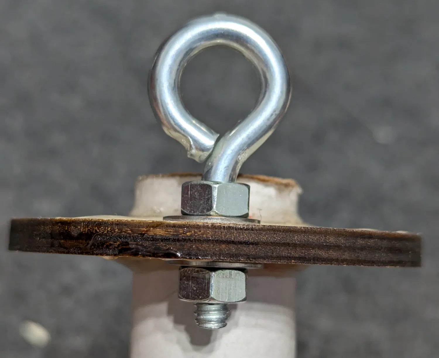
Put a nut and a washer onto the eyebolt.

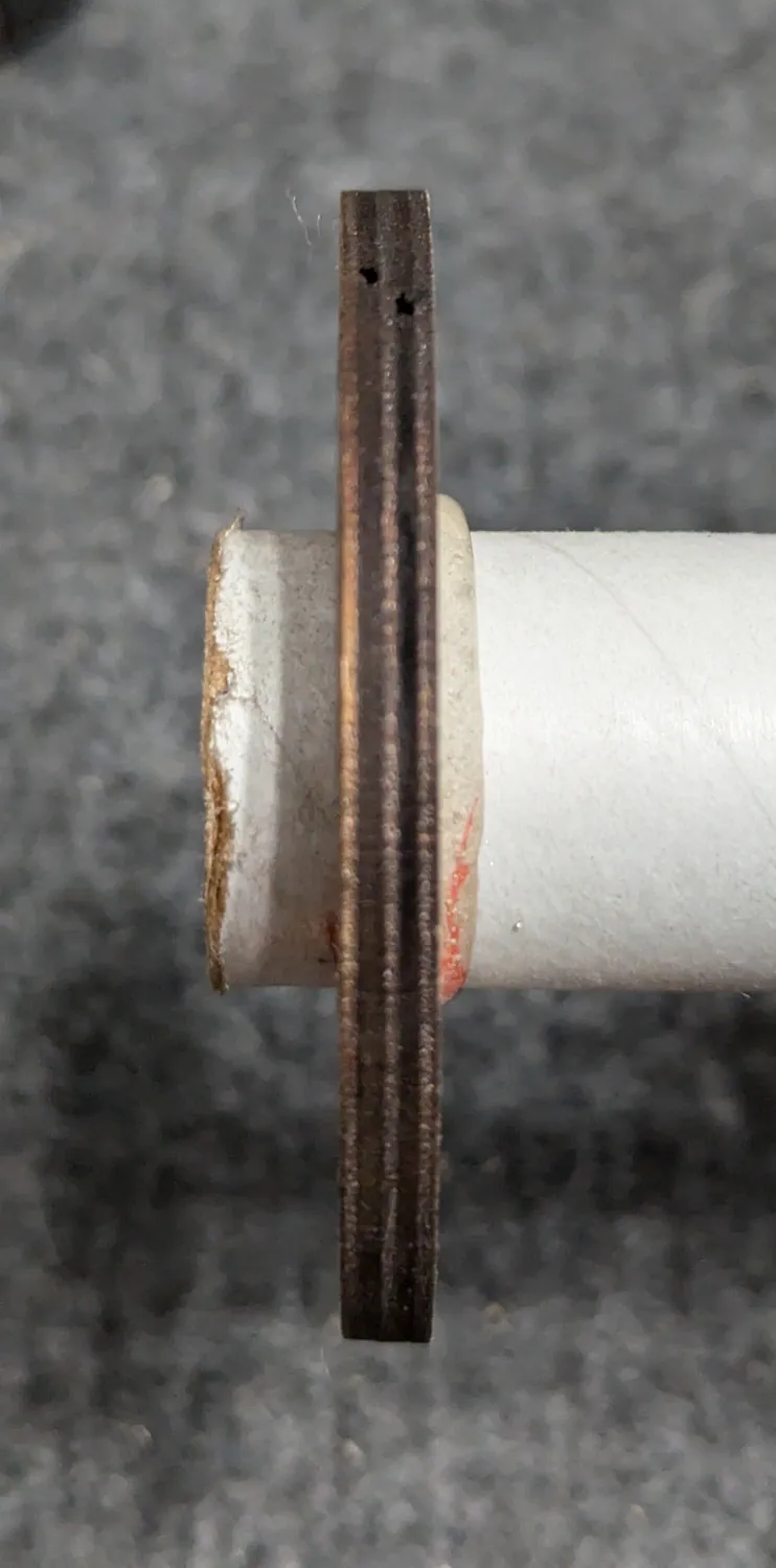
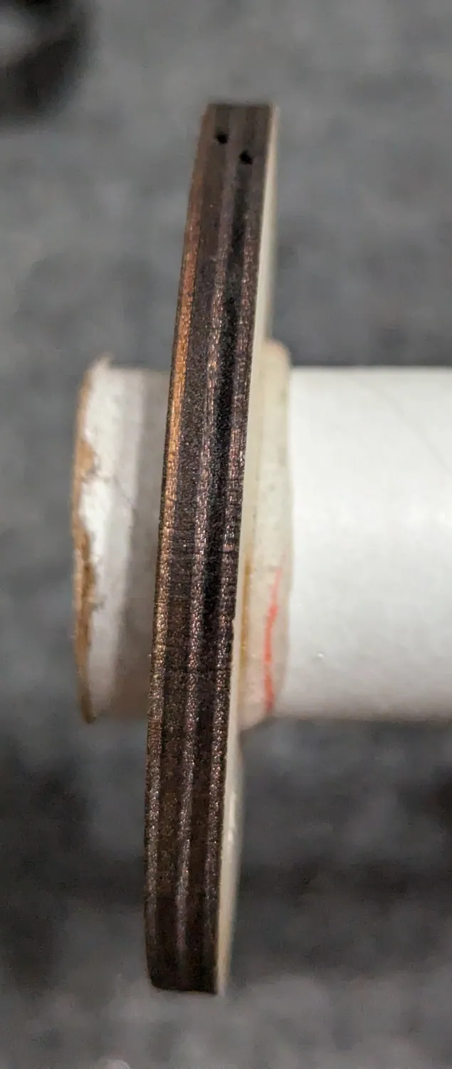
Pass the eyebolt through the hole in the forward centering ring from the forward side.

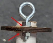
Add the second washer and nut on the back and tighten with the two 7/16 wrenches.
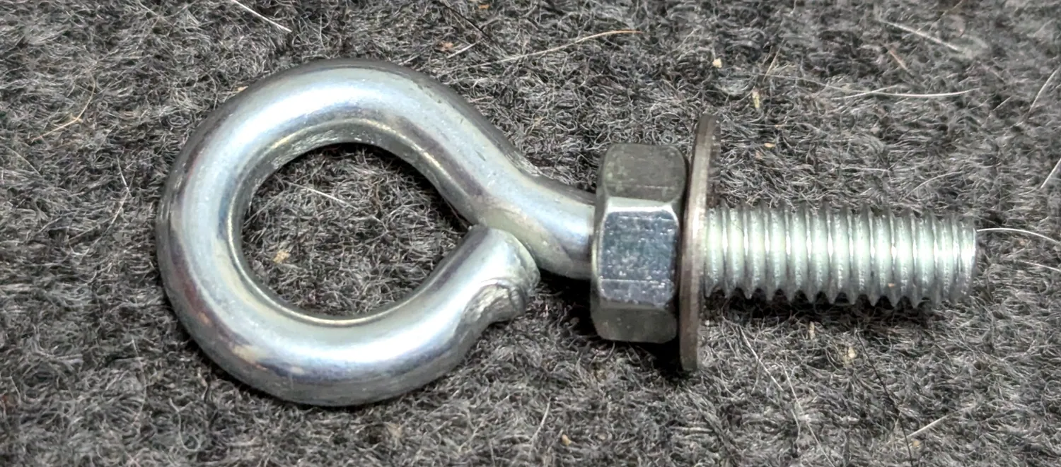
¼-20 eyebolt with nut and washer.
Eyebolt through the ring, washer and nut on both sides.
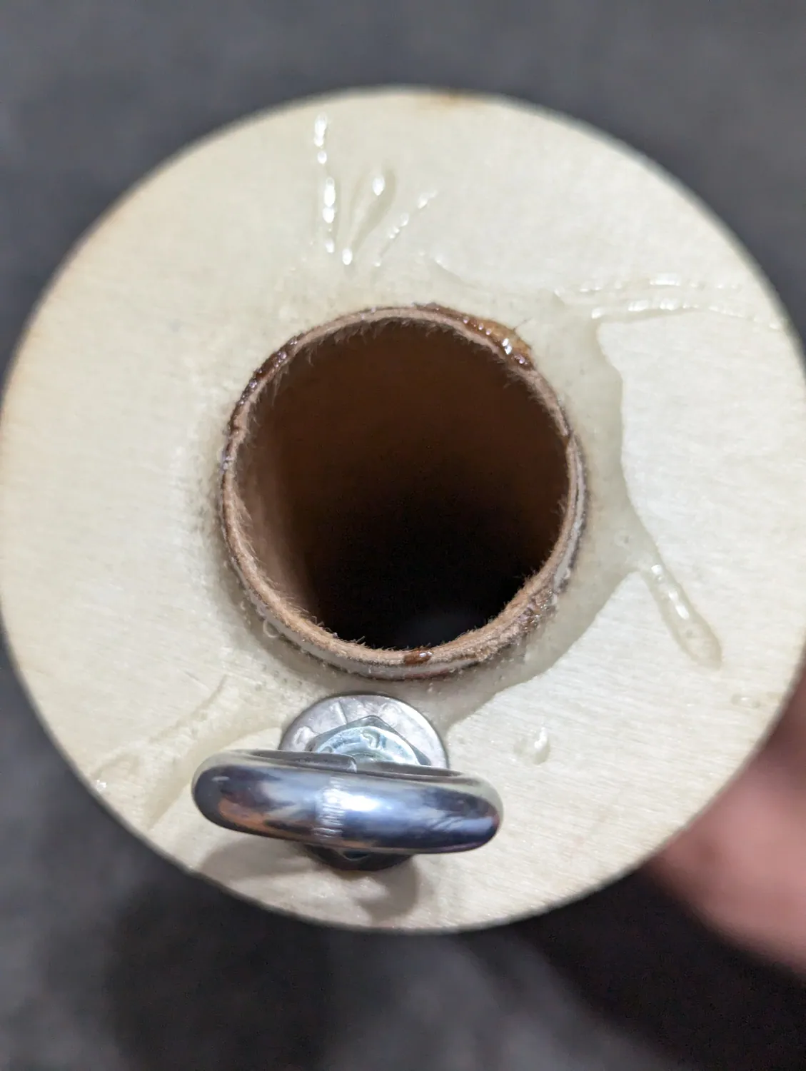
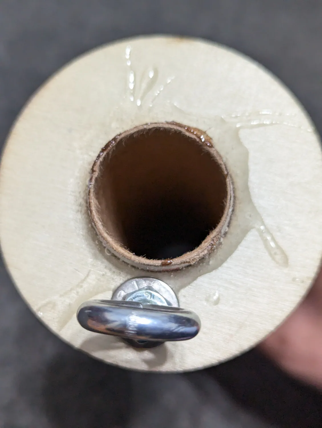
Looking down the motor mount — eyebolt hardware on the back of the forward ring.

Epoxy the back side of the centering rings

5-minute epoxy

Fillet epoxy into the joint between each centering ring and the motor mount tube, on the side you have not glued yet.

Put epoxy over both eyebolt nuts and washers. Not a lot — just enough that they can never back off.

Stand the assembly motor-mount-down to cure.
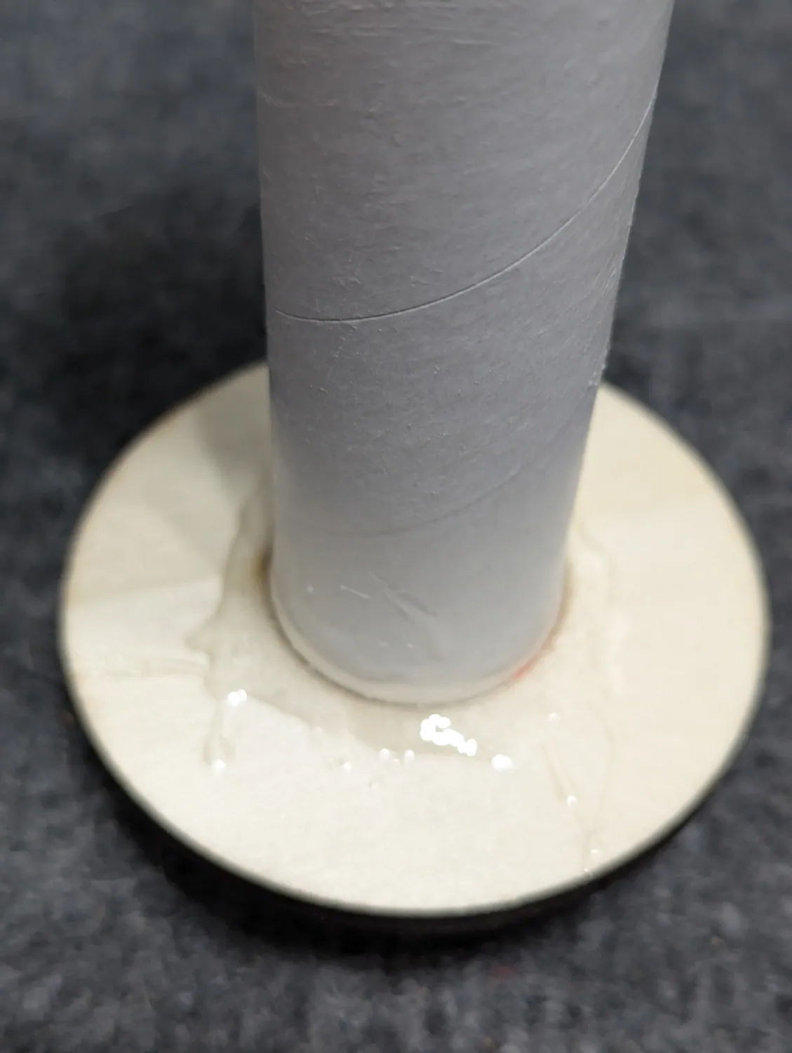
Standing motor-mount-down with fillets on the forward ring.
Ring-to-tube joint filleted all the way around.
Epoxy over the eyebolt nut and washer so they cannot loosen.

Test fit the motor mount in the body tube

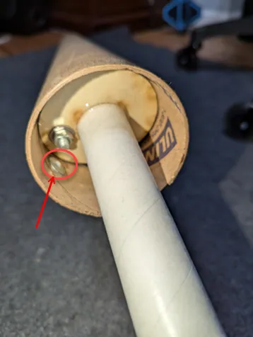
Slide the motor mount into the body tube. Go in at a slight angle to clear the aft rail button nut.

Sand the outside diameter of the centering rings as needed. You want snug — it should slide with some resistance, not drop in.
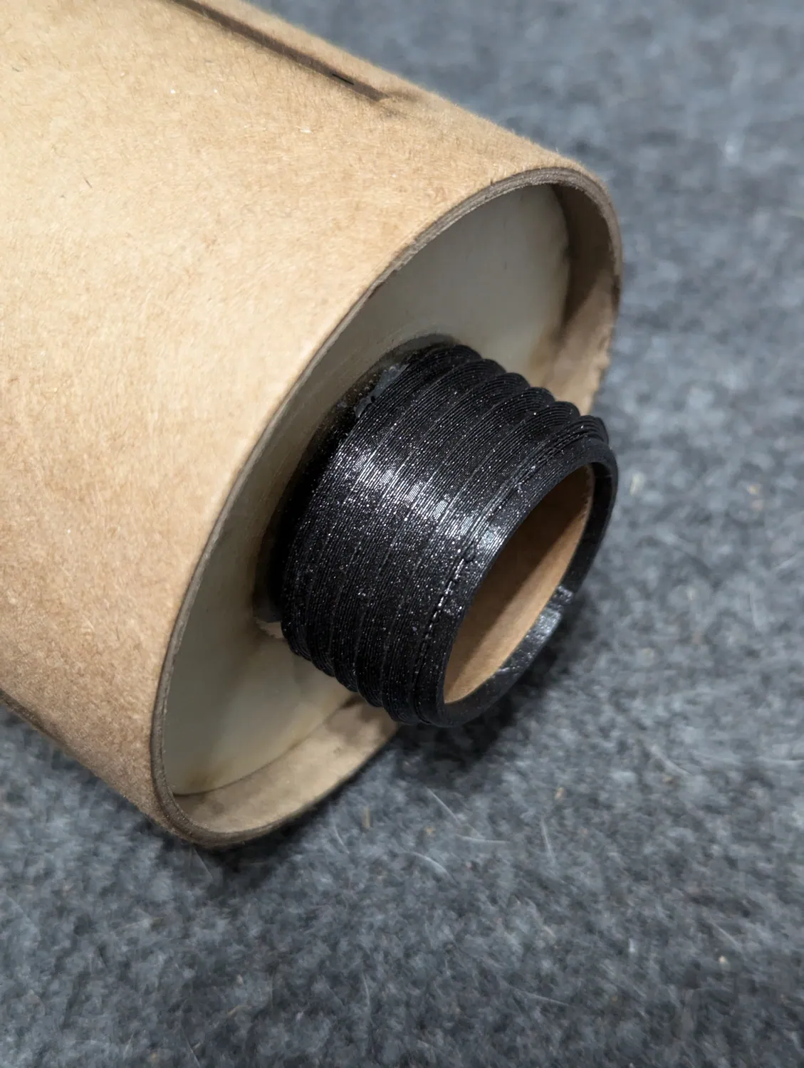
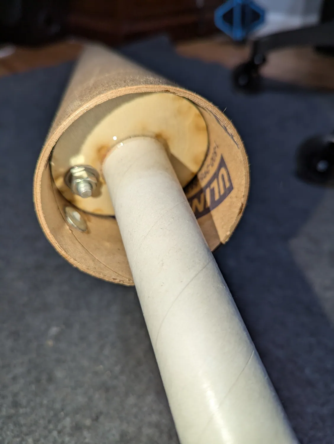
Do this dry, and get the fit right now. Once there is 15-minute epoxy inside the body tube you have one shot.
Motor mount entering the body tube.
Enter at an angle to clear the rail button hardware.

Tie the Kevlar cord to the eyebolt

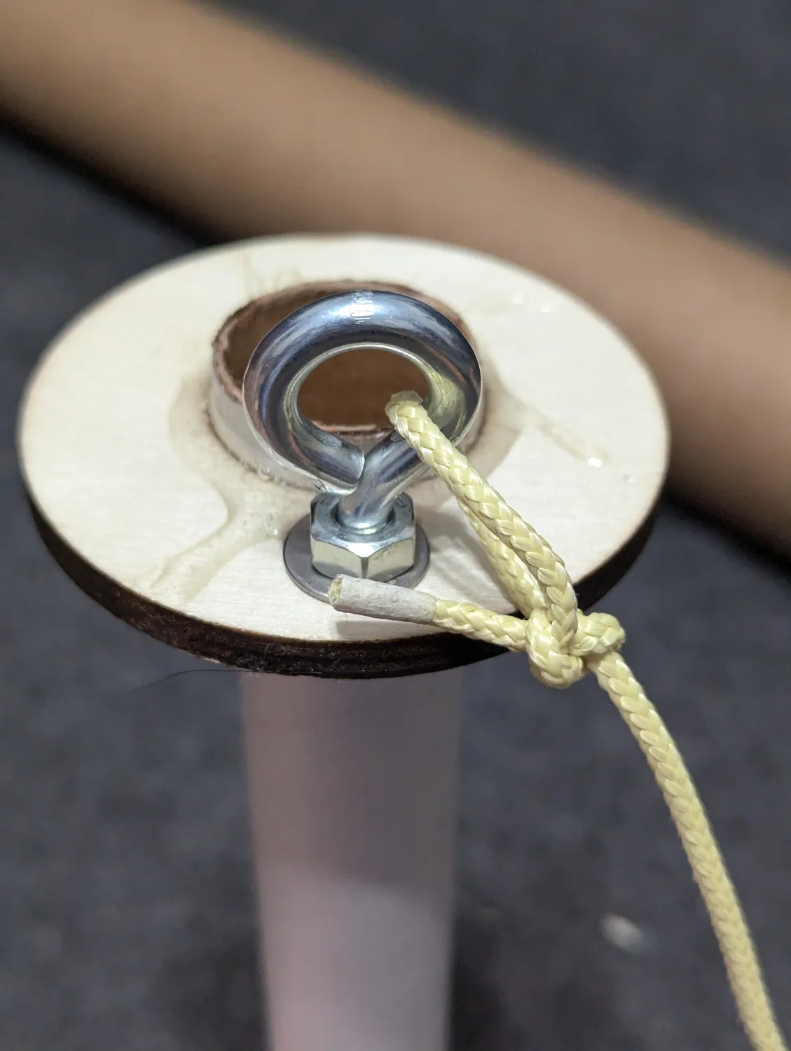
Tie the 5 ft Kevlar cord to the eyebolt with a bowline.

A bowline gives you a fixed loop that will not slip and will not jam shut under shock load, which is exactly what you want on the recovery anchor.
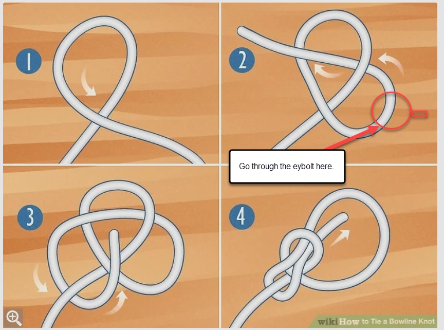
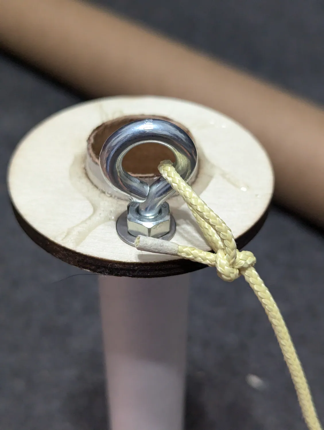
Rabbit out of the hole, around the tree, back down the hole. Then dress it and pull it tight before you trust it.
Pull the correct side tight. The last frame of the diagram shows which end to load — pull the wrong one and the knot capsizes instead of setting.
Bowline, step by step. Frame 2 is the part the generic references leave out: the line goes through the eyebolt there. (Diagram: wikiHow, annotated for this build.)
Finished bowline on the eyebolt.

Protect the Kevlar from epoxy

Tape over the cord where it meets the eyebolt with masking or painter's tape.

Feed the loose end of the cord down through the motor mount tube so it is out of the way while you glue.
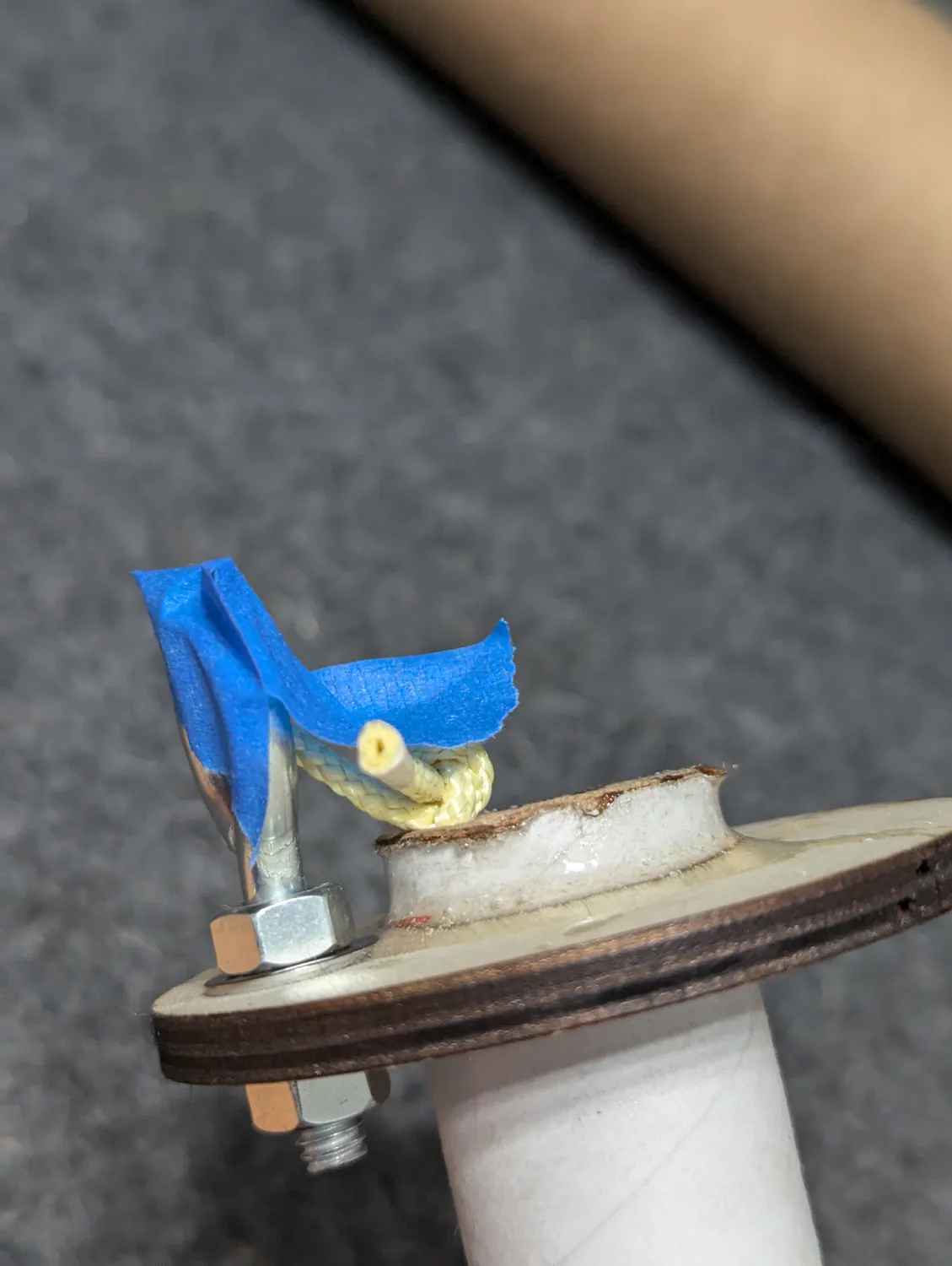
Epoxy soaked into the Kevlar makes it stiff and brittle right where it takes the most shock. Tape it.
Bowline on the eyebolt before taping.
Blue tape over the cord and eyebolt.

04Install the Motor Mount

15-minute epoxy from here — you need the working time. Read all four steps before you mix.

Mark your epoxy stick

Hold a stir stick against the motor mount and mark the distance between the two centering rings on it.

That mark tells you how far down the body tube to reach when you put the glue ring inside.
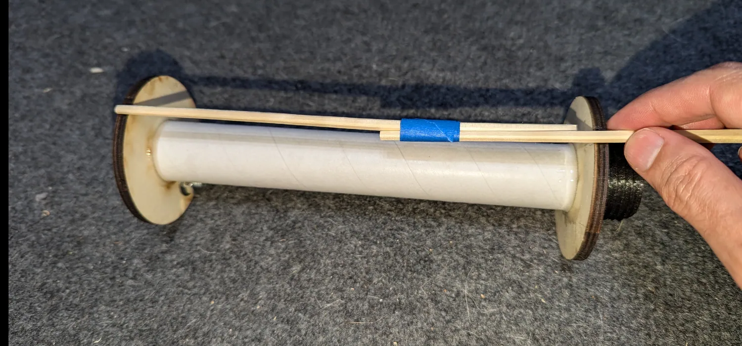
The sticks in the current kits are long enough that you do not need to tape an extension on.
Stick marked against the motor mount.

Put a ring of epoxy inside the body tube

15-minute epoxy

Using the marked stick as your depth guide, lay a ring of epoxy around the inside of the body tube where the forward centering ring will land.
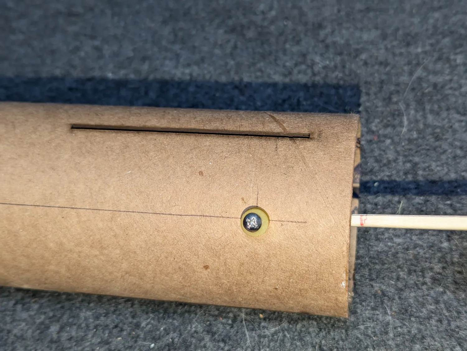
Reaching in with the marked stick to lay the internal glue ring.

Start the motor mount in and add epoxy

15-minute epoxy

Partially insert the motor mount.

Spread more epoxy at the aft end of the body tube where the aft centering ring will sit.

Put a little epoxy on the rail button backing nut and the tube around it.
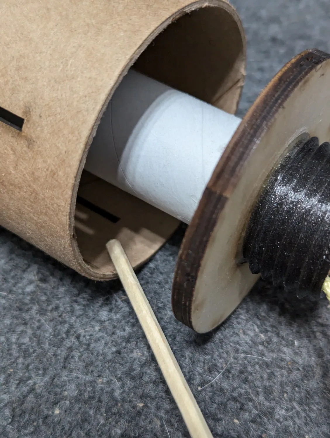
Motor mount started into the body tube.
Epoxy over the rail button weld nut on the inside.

Seat the motor mount

Push the motor mount the rest of the way in until it is fully seated as shown.

Let the epoxy cure completely before you go on.
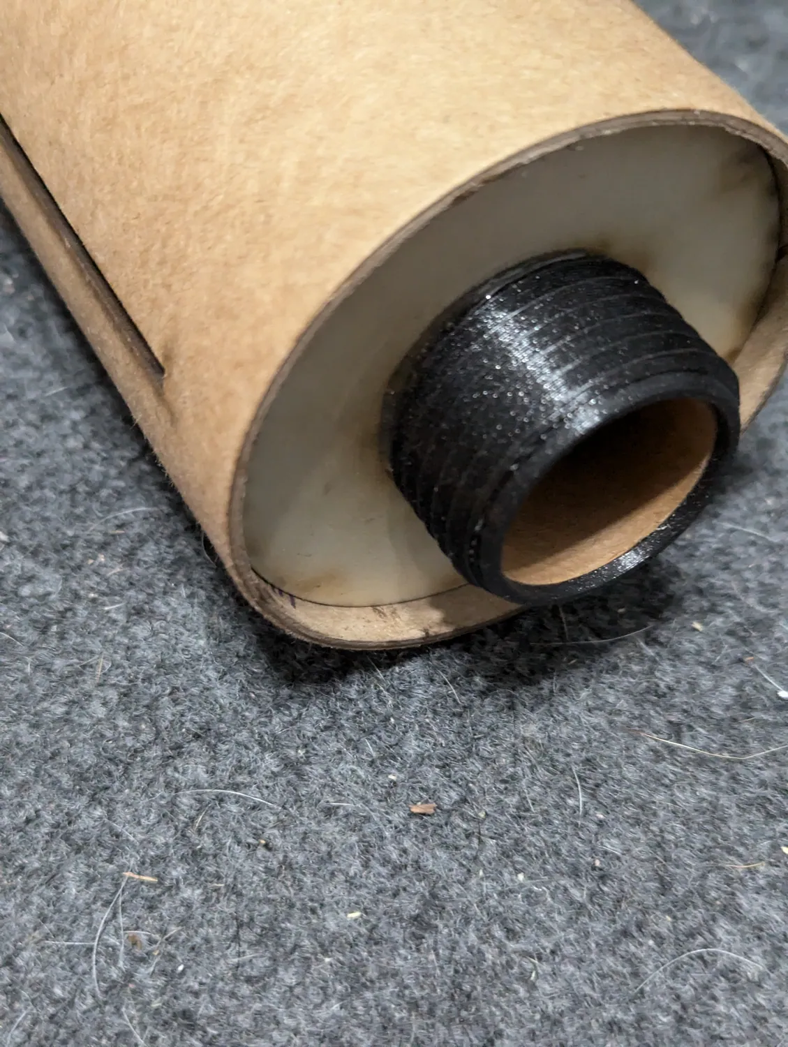
Do not move to the fins until this is fully hard. The fins locate off the motor mount.
Motor mount fully seated.

Epoxy the aft joint

5-minute epoxy

Fillet epoxy into the joint between the aft centering ring and the body tube, all the way around.
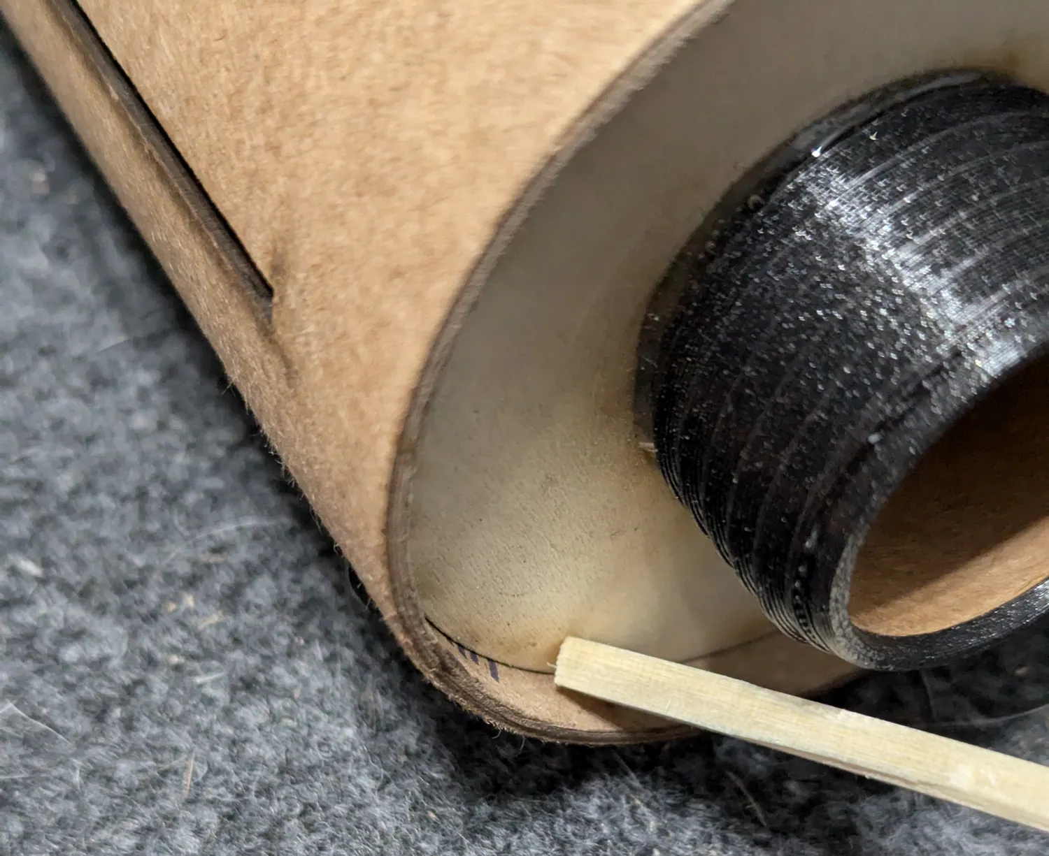
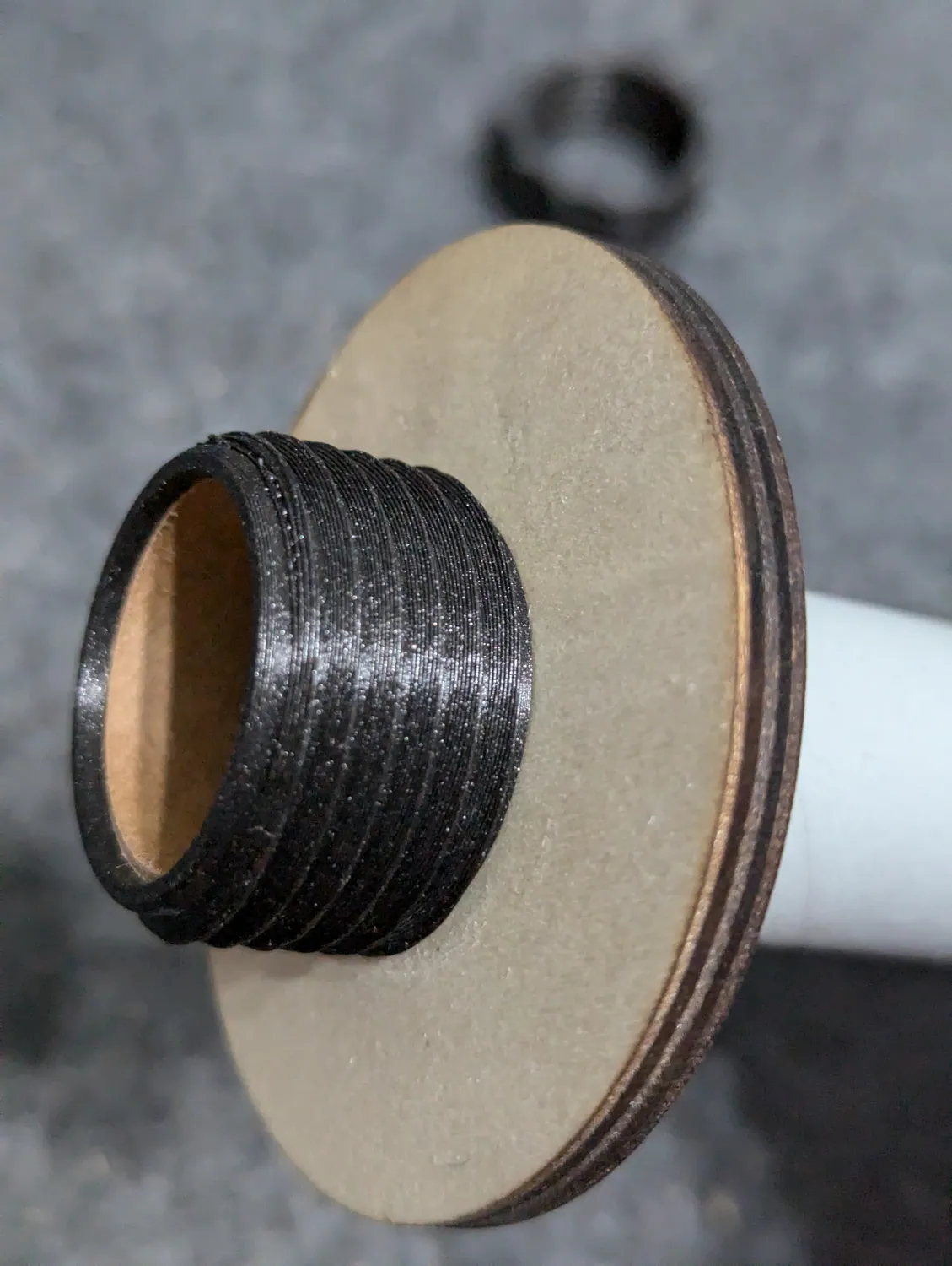
Keep epoxy off the retainer threads. Easiest way: thread the retainer screw cap on first, glue, then take it back off.
Filleting the aft ring to body tube joint.

Watch: Reading the motor code

While step 27 sets. If the class is ahead, it can play before lunch while the install cures.

How to decode a motor designation like G74W-6 or H128W-14, and why average thrust, not just the letter, decides whether a motor is safe for a rocket.

05Fins

Three fins, through-the-wall into the motor mount. Alignment here is what makes the rocket fly straight.

Test fit the fins

Slide each fin into its slot dry. The fin root should reach the motor mount tube and the fin should stand straight out along a radius — not leaning.

Wood thickness varies, so you may need to sand the slots to get a fin to go in.
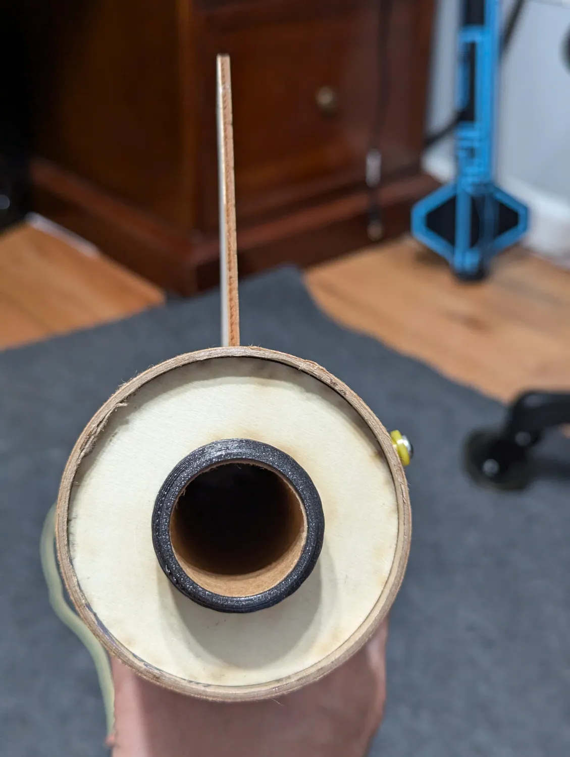
Sand the slot, never the fin. Thinning the fin weakens it and opens up a gap you cannot fill.
✓Fin standing straight out, root down on the motor mount.
Fin standing straight out, root down on the motor mount.
✕Fin leaning in the slot — not square to the tube.
Fin leaning in the slot — not square to the tube.

Epoxy the fins

5-minute epoxy

Put epoxy along the root (back) edge of the fin and slide it into the slot.

Make sure the root contacts the motor mount tube and the fin is aligned before the epoxy sets.

Do one fin at a time.
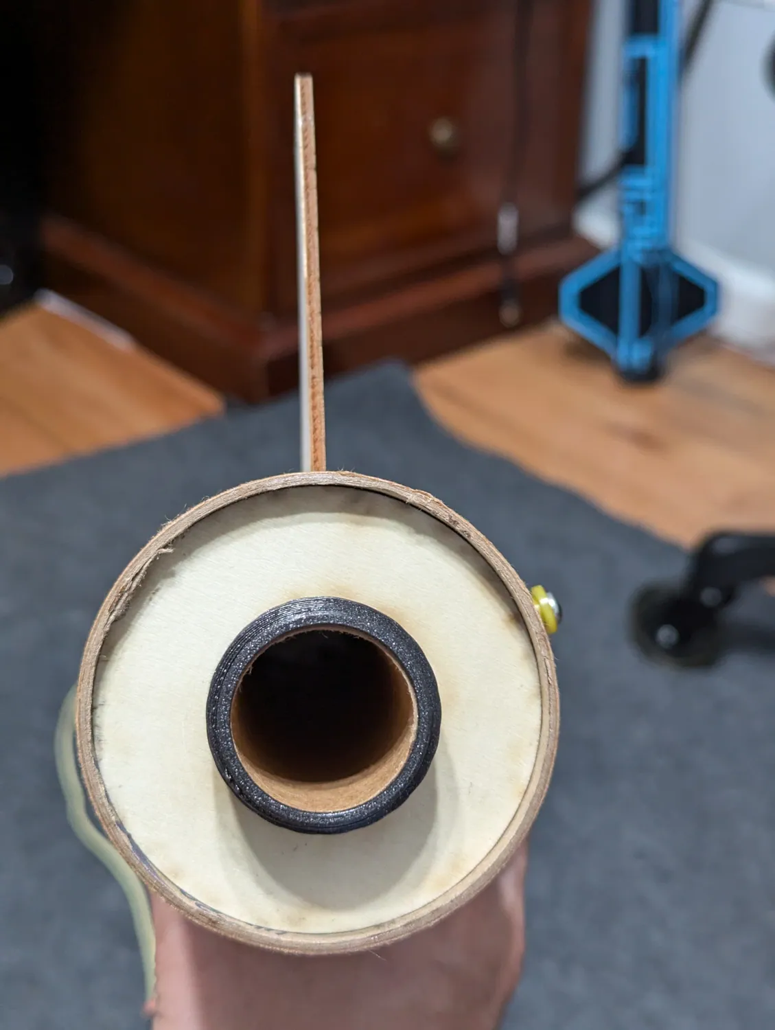
✓Fin seated square against the motor mount.
Fin seated square against the motor mount.
✕Fin canted in the slot — pull it and reset before it cures.
Fin canted in the slot — pull it and reset before it cures.

Watch: Thrust curves and the delay

While the first fin sets (step 30).

How to read a thrust curve: total impulse, peak thrust and burn time, and what a wrong delay looks like on the field.

Watch: Motor sizes, types and safety

While the second fin sets (step 30).

The common motor diameters, black powder versus composite, and the program’s motor handling rules.
Watch: Why simulate, and what tools exist

While the third fin sets (step 30).

Why we simulate before flying, the two common tools, and what the CP and CG markers and the stability number look like in OpenRocket.

Fillet the fin roots

5-minute epoxy

Every fin gets an epoxy fillet on both sides where it meets the body tube — six fillets in all. You do them two at a time, letting gravity hold the epoxy in the joint.
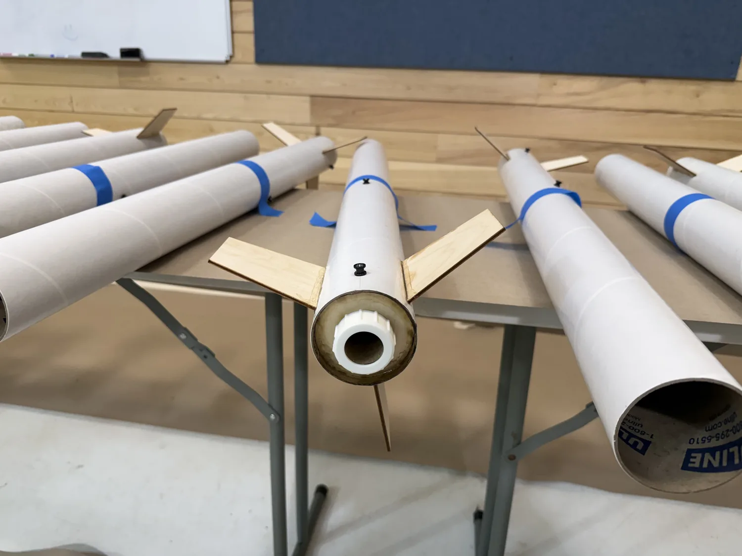
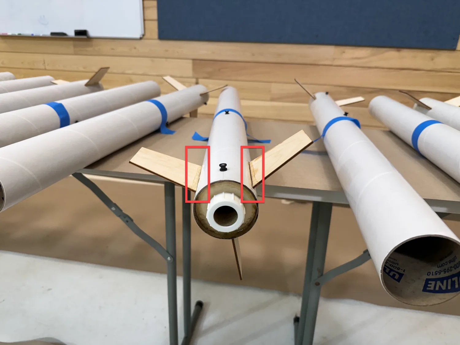
  1. Lay the rocket on the table resting on one fin, so the other two fins point up in a V. Roll it until both raised fins are at the same angle — the joints between those fins and the tube should face straight up.
  2. Mix a small batch of plain 5-minute epoxy. Do not thicken it or add anything to it.
  3. Dab the epoxy into the joint along the root of each raised fin, on the side facing up. Work from the front of the fin to the back so the whole root is covered. It will settle into a smooth fillet on its own.
  4. Wait 5 minutes for it to set.
  5. Roll the rocket onto the next fin so a fresh pair of joints faces up, and repeat.
  6. Do it one more time. After three rounds every fin root is epoxied to the body on both sides.
Small dabs, not a bead. Plain 5-minute epoxy is thin enough to flow into the joint by itself; a big bead runs down the tube.
Do not move the rocket until the epoxy has set. If it rolls while wet the fillet slumps to one side.
Rocket resting on one fin with the other two pointing up equally. Epoxy goes into the two upward-facing root joints.
The two joints to fill in this position. Roll the rocket and repeat twice more for the other four.

Watch: Building a rocket from scratch in OpenRocket

During fillet round one (step 34).

Starting a new OpenRocket design, adding the parts of a simple rocket in the right order, then opening the program’s BR-1 file and understanding what you are looking at.

Watch: Stability with and without a motor

During fillet round two (step 34). This one leads straight into the homework.

Adding a motor to the OpenRocket model and what it does to CG and stability, then running a simulation and reading apogee, rail-exit speed and the optimum delay.
06Recovery Harness

Kevlar to nylon, nylon to nose cone, and a loop in the middle for the parachute.

Tie the nylon shock cord to the Kevlar

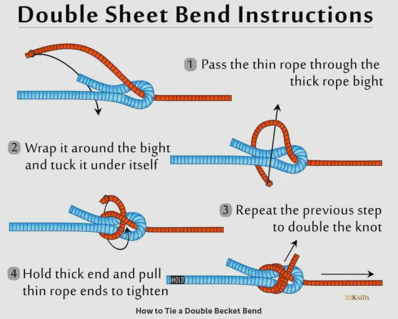
Join the 10 ft nylon cord to the Kevlar with a double sheet bend. A sheet bend is the right knot for joining two lines of different diameter, and doubling it keeps it from working loose in slick nylon.

Make the bight in the thicker line (the nylon) and pass the thinner line (the Kevlar) through it.
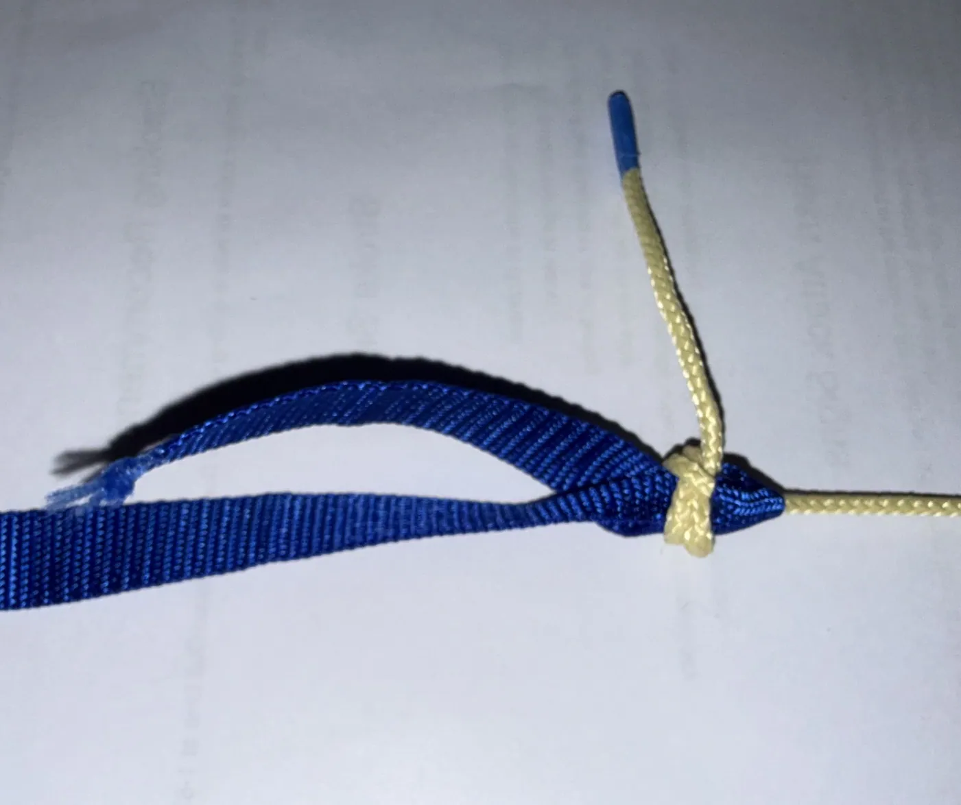
In the photo the blue rope is the nylon (bigger) and the yellow rope is the Kevlar (smaller).
Pull the thick end and the thin ends in the directions the last frame shows. Loaded the wrong way the bend slips, and slick nylon is unforgiving about it.
Double sheet bend, step by step. (Diagram: 101Knots.)
Finished double sheet bend joining nylon to Kevlar.

Tie the nylon to the nose cone

Tie the free end of the nylon shock cord around the bar inside the nose cone shoulder with a bowline.
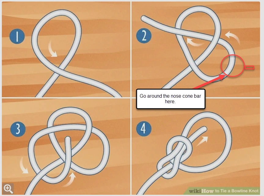
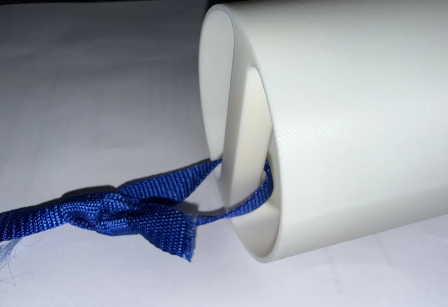
Pull the correct side tight. The last frame of the diagram shows which end to load — pull the wrong one and the knot capsizes instead of setting.
Same bowline — at frame 2 the line goes around the bar inside the nose cone shoulder. (Diagram: wikiHow, annotated for this build.)
Nylon tied around the nose cone bar.

Make the parachute attachment point

Tie an overhand knot about 12 inches down from the nose cone attachment point.

Fold the shock cord in half at that spot and use the looped end to tie around the rest of the cord, making a fixed loop.

This is where the parachute clips in at the field.
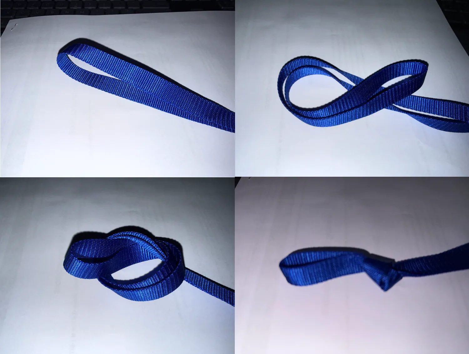
Parachutes are loaned out on launch day rather than included in the kit — they run about $15 each, and keeping them program property keeps the participant fee down. Hand yours back after recovery.
Folding the cord and tying the loop, in four steps.

07Finish & Homework

Decorate your rocket

Paint, temporary tattoos, and other decoration are all fair game. Prizes may be given for the best-designed rocket.

Skip stickers and tape — at flight speed they peel off and change how the rocket flies.

Homework: simulate your rocket in OpenRocket

Learn to simulate your build. Play with launch angle and wind to see how far you might have to walk, and improve your odds of getting the rocket back.

Start from the program's own BR-1 model rather than building the airframe from scratch — open it in OpenRocket, then change motors, mass and conditions and watch what happens.